Description
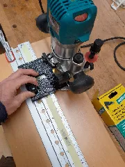
PDFI wanted a LED light for my Bosch GOF 1250 CE router.
(There is a version that has LED included, but i don't have thist one.)
I wanted a switch, so I can use the light, also when the router is not running. And I wanted to be able to switch the light off, when changing the bit - without sunglases ;-)
I didn't want a battery solution.
So I designed a case for a LED-Driver (Self Electronics SLT3-350ISC) and a switch (opening 13x19mm) to mount at the outside of the machine. Only one screw is needed - the hole does already exist.
The power supply I took from inside the handle - at the power button. There is a way for the two (L , N) wires inside the machine. I had to take off the top and the base of the machine to put the wires inside.
!Take care about the motor-brushes when taking out / reassembling the base together with the motor-rotor!
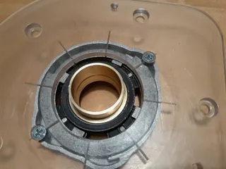
I didn't redesign the original black cover around the shaft. But I had to adjust it: holes for the input and output wires, creating some more space (with dremel) for the solderd wire-connections.
As I used a LED Ring there was the Problem, that it coverd the two screws of the original cover. The first attempt was to use a bigger (70mm) LED ring, giving space for the screws. But I didn't like it, because it was so big, that the visibility was worse. So I used a 50mm LED Ring. I designed a “holder” witch is mounted with slightly longer M4 screws together on top of the original cover. The LED ring sits on top of it an is hold by a “cover”. There are two holes in the side of holder an cover to secure the cover with small screws. But the screws are not needed as the cover has a tight press-fit. The roughness of the print helps to hold the cover in place.
The whole setup messuers +9mm - so it is still enough space for the wrench.
!It was neccesary to use the thiner wires (came with the LED ring) to realize a slightly flexible connection around the corner! I secured the wires with some hot glue.
The “case” needs support-material for printing - for the “holder” the result is better with support.
Assembly:
- Print the three parts
- Put wires L + N in the machine
- melt two M3 Threaded inserts in the case
- screw the driver in the case (there ar two channels under the driver for the wires)
- put the wires for the switch through the opening - solder the wires to the switch (due to limited space, keep the wires short)
- mount the ready cover on the machine
- prepare the original black cover with the holes and the space for input and output wires
- put the wires in the original black cover
- mount the LED ring in the printed “cover”
- put the thin wires in original black cover
- solder the input and output connections and cover them with shrinking tube
!limited space! - mount the “holder” together with the original black cover (2 longer M4 srews are needed)
- clip the “cover” - with the LED ring inside - on top of the “holder”
!wires have to be short!
!hotglue helps to avoid breaking out of the connections on the LED platine!
Result:
Bright daylight under the router :-)
May it be useful…
----
Switch: https://www.berrybase.de/wippschalter-1-polig-schwarz-on-off-io-beschriftung?c=2357
2x M3 Threadet inserts M3 (5mm)
LED ring 50mm: https://hc-maschinentechnik.de/LED-Ring-50-mm-Weiss-Weiss
----
Tags
Model origin
The author marked this model as their own original creation.


