5:1 Planetary Gear Reducer for Nema 17 Stepper Motors Ball Bearing Version
Description
PDFPartlist:
Befor printig all parts for a large gearbox try one stage and test for tight tollerances!
Partlist for the first stage and single stage versions:
- 1x Packer
- 1x Sun_1
- 1x Ring
- 3x Planet_bearing
- 1x nema_adapter_45deg_stack
- 1x carrier_bearing (print with support for inner bearing place)
- 1x cap_bearing
- 3x M3x12 buttonhead screw (Head diameter > 6mm or aditional 3 washers m3)
- 4x M3x30 countersunk head screw
- 4x M3 heat set inserts short (for 4mm holes like ruthex ones)
- 3x M3 heat set inserts long (for 4mm holes maybe short will work too)
- 1x ballbearing id=30mm, od=37mm, thicknes=4mm
- 3x ballbaring id=3mm, od=7mm, thicknes=3mm
- 1x ballbaring id=5mm, od=8mm, thicknes=2.5mm
for every additional stage:
- 1x carrier_bearing_stack
- 1x cap_bearing
- 3x Planet_bearing
- 4x M3 heat set inserts short (for 4mm holes like ruthex ones)
- 1x Ring
- 3x M3x12 buttonhead screw (Head diameter > 6mm or aditional 3 washers m3)
- 4x M3x20 countersunk head screw
- optional 1x M3x6 zylindrical head, head turned down to 5mm diameter
- 1x ballbearing id=30mm, od=37mm, thicknes=4mm
- 3x ballbaring id=3mm, od=7mm, thicknes=3mm
- 1x optional ballbaring id=5mm, od=8mm, thicknes=2.5mm
Assembling:
preperation for every stage:
- insert 3x8x3 bearings in planet_bearing
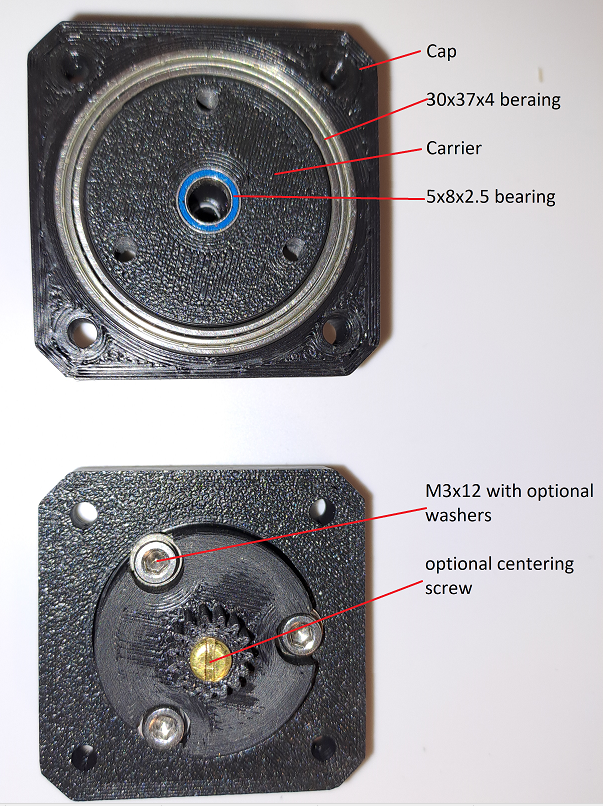
- insert 30x37x4 bearing inside cap_bearing
- clean support out of the hole in the carrier
- if using as single stage or doing the optional M3x6 for extra centering the stages together: insert 5x8x2.5 bearing inside carrier_bearing od carrier_bearing_stack
- inseart heat sets into the bigger holes of nema_adapter_45deg_stack and in the carrier_bearing
- optional screw the M3x6 with the turned down head from the geared side in the carrier_bearing_stack (i used a brass screw insertet into a mini drill and a file to turn the head to 5mm. Test wit the 5x8x2.5 bearing if the head diameter is small enough.)
- insert the carrier_bearing(_stack) into cap_bearing and screw the 3 M3x12 from the topside to fix the carrier inside the cap. Try to get the screws as good as possible in an 90 deg angle in, these will be the axles for the planet gears. I used a M3 tap for preparing the holes but it should also be possible without taping.


Assembling the first stage
- put the packer on yout nema17 Motor (flat side facing up)
- put the sun_1 on the Motor axle be acrefull the sun gear must be realy close to the packer. Hint: Some moters have the D-shaft not cut down to the base. Maybe you need to design a distanz adapter and use longer screws later
- get your first set of carrier and cap and place the planet gears (facing the bearing opening to the carrier) on the ends ot the M3x12
- put the ring arund the planet gears
- hold the carrier assembly facing the gears up and insert the motor with the sun gear carefully (Building one stage use the carrier_bearing, building more stages using one with a carrier_bearing_stack)
- turn all around without lousing your gripp and place a adapter_nema17_45deg_stack on top (the counter sunk holes facing up) and align the counter sunk holes with all other layers of parts and the holes in the motor
- use the M3x30 to hold the stage together (using here longer screws if you need a distance pice in step 2)

The tip of the motor axle should now rest in the inner bearing of the carrier. By loosening the screws one turn and tightening them while the motor running the parts will better line up.
Assembling all following stage:
Redo the steps from the first stage starting by step 3. The parts from the steps 1 and 2 are not needed again because the packer as a rest for the planet gears is replaced by the flat surface of the previous carrier and the nema adapter, the sun gear is also provided by the carrier of the previous stage.
Use in step 7 the M3x20 instead of M3x30 and alin the hole stage 45 degree tilted to the previous stage and use the heat set inserts in the nema adapter.
Diamensions of the output axle:

As a example i added a 30 teeth gear wit a Modul of 1mm, 9mm thick as a output.
Limits
I tested the model in ASA, printed at 0.2 Layerhight, 0.4mm Nozzle. Two stages wer good. The second stage was also usable but under harder load (wich an nema 17 can provide by a gear ratio 1:125) it started sliping Printig with tighter tolerances and may be in Nylon would help. Also a finer Nozzle might help to get the gears in a better shape and better fitting.
Tags
Model origin
The author remixed this model.
Differences of the remix compared to the original
Added space for Ballbarings on planet gears and output shaft. Aditionaly added the possibility to stack multiple of those gearboxes to get higher reduction rates. In this process also an adapter is designed to mount the geared motor through nema17 mounting holes. Everey aditional multiplies in the gear ration so the Photo of a 3 Stage modell has a ratio of 1:125.

