Jar lid - Combination lock
Description
PDFUse
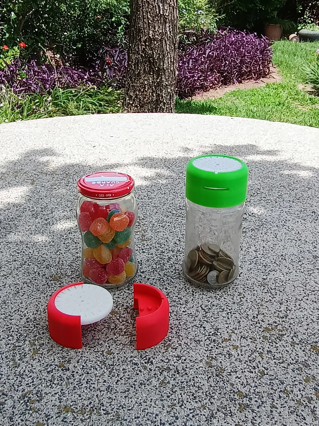
The lock is for a lug jar 63-2030, which is the most commonly use jar for jam in my country.
The lock can be applied to a jar with or without it's original lid.
The model
This model is inspired by a lock design a saw in the video [525] Soviet Car Gas Cap Lock Decoded by LockPickingLawyer.
I made this design with two main objectives:
- So I could attempt to decode (for fun).
- To make some improvements I thought while watching the mentioned video (I got interested, and since I have a 3D printer…).
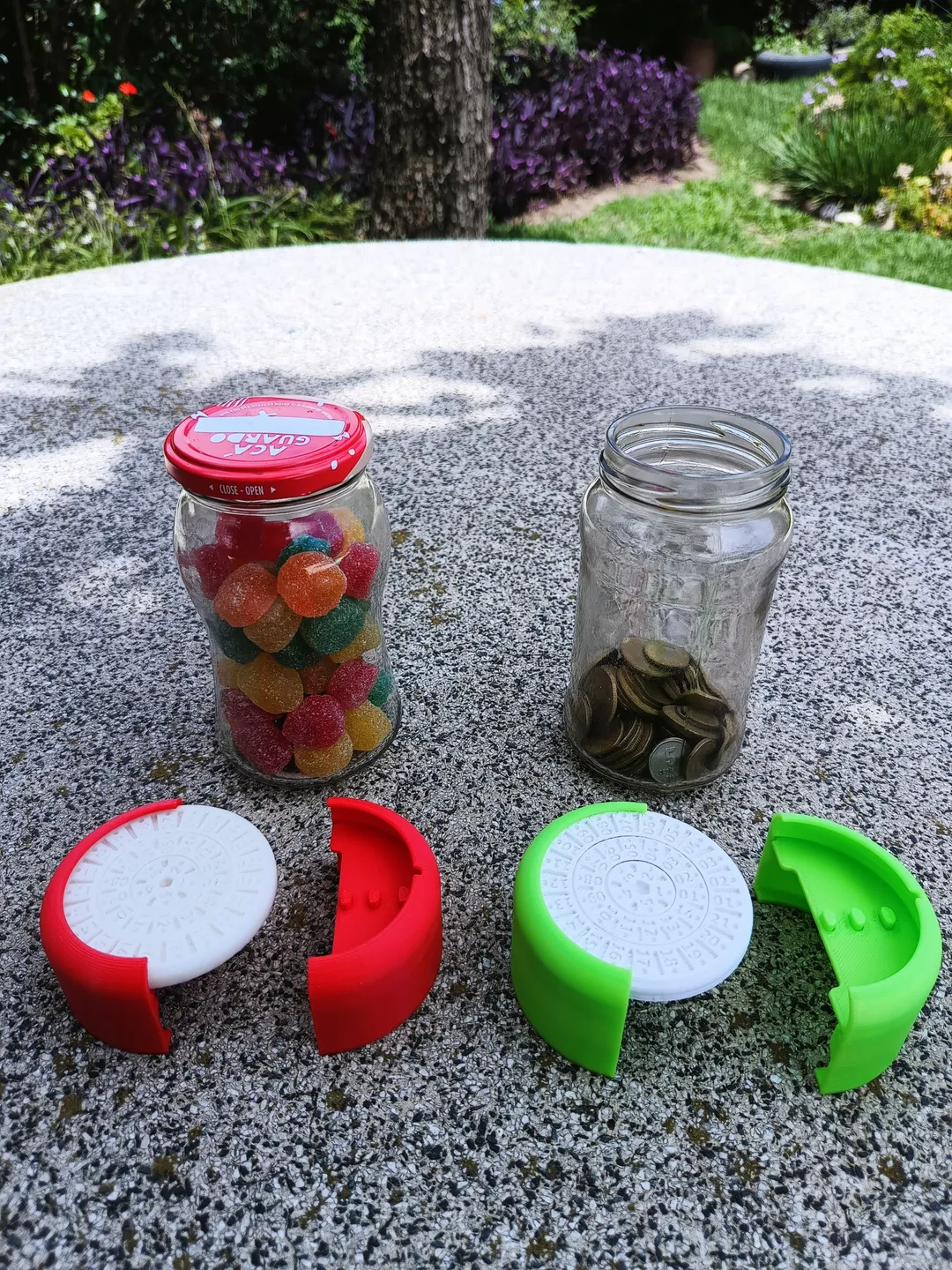
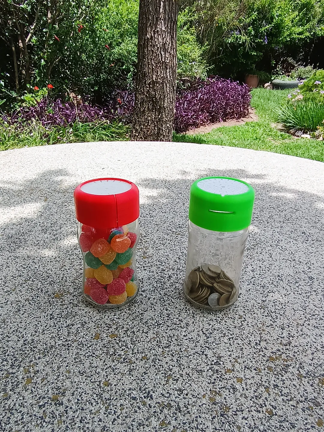
To give the design some use after I play with it, I modeled the lock to fit an standard jam jar lid, as show in the pictures.
Since I put to much effort in this toy lock (and I liked the final result), decided to share it. I consider this an original design because of the improvements I added (mainly the ability to change the code, plus the extra dial).
Some uses of this print would be:
- To keep simple thing away from others (candy, spare change or whatever fits the jam jar).
- To practice lock-picking in this particular type of lock.
- To give someone a gift, such that they have to decipher the combination to open it.
Please keep in mind that this is relative easy to decode and it's made from plastic (basically a toy), so you shouldn't use it to guard anything significantly important. As said before, candy is fine, some spare change too.
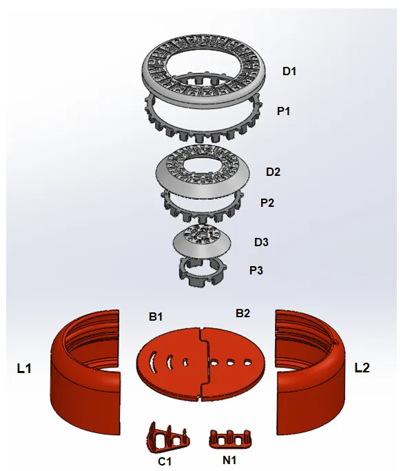
Parts List
| D1 – Dial 1 v1.0 | D2 – Dial 2 v1.0 | D3 – Dial 3 v1.0 |
| P1 – Pin - Dial 1 v1.0 | P2 – Pin - Dial 2 v1.0 | P3 – Pin - Dial 3 v1.0 |
| L1 – Lid v2.0 | B1 – Base v1.0 | C1 – Curved clips v1.0 |
| L2 – Lid 2 v2.0 | B2 – Base 2 v1.0 | N1 – Bolts v1.0 |

There is a version for the to lids (Lid 3 v2.0 and Lid 4 v2.0) with a slot for coins, to avoid having to use the code just to put money in.
The assembly steps remains the same.
Assembly steps
Step 1: Bases assembly
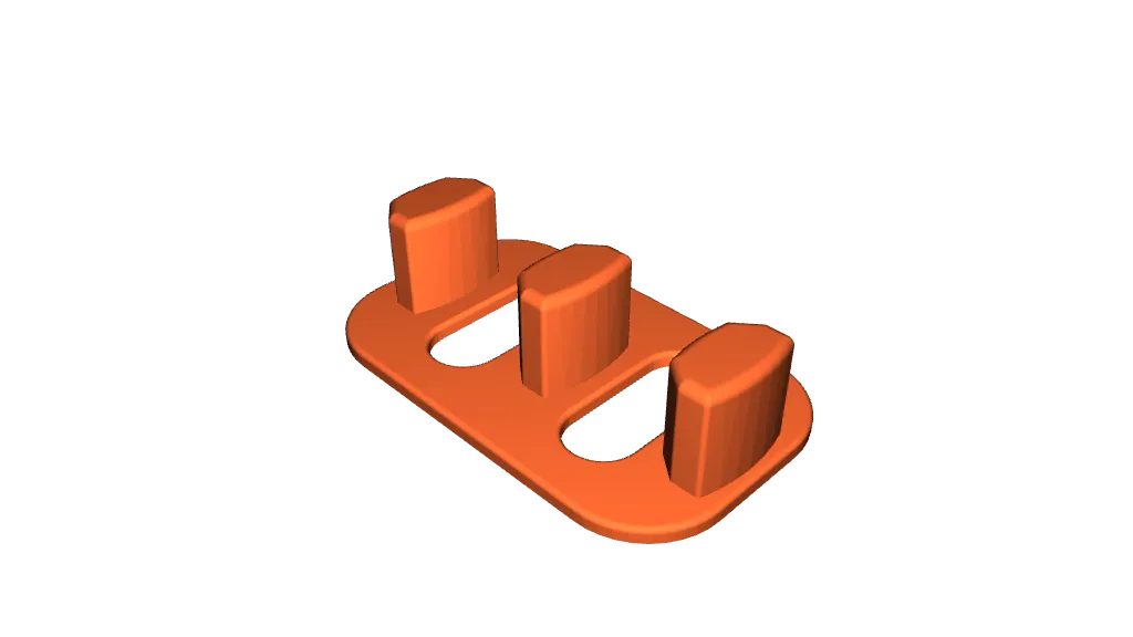
Assemble the bases by inserting the bolts (N1) and the blocking curved clips (C1) in their corresponding bases (B1 and B2).
The assembly steps are as follows.
| 1.a Parts: B1 and C1 | 1.b Parts: B1 and C1 |
 |  |
| 1.c Parts: B2 and N1 | 1.d Parts: B2 and N1 |
 |  |
Step 2: Selection of the code for the lock
Assemble the dials by inserting the corresponding pin wheels.
Selection of code: Each pin wheel (P1, P2 and P3) has a small hole in it to identify the true gate. By aligning this hole with a number, said number is set to be part of the code. This must be done for the three dial wheels (D1, D2 and D3).

The assembly steps are as follows.
| 2.a Parts: D1 and P1 | 2.b Parts: D1 and P1 |
 |  |
| 2.c Parts: D2 and P2 | 2.d Parts: D2 and P2 |
 |  |
| 2.e Parts: D3 and P3 | 2.f Parts: D3 and P3 |
 |  |
Step 3: Assembly of the first half of the jar lid
Assembly of the half that contains the bolts of the lock.
In this step, the base whit the bolts (B2) are inserted in the half lid that contains a notch above in the middle (L2). This is done by aligning the notch in the base whit the internal groove of the half lid, like its show in the below pictures, and then rotating the base until it reaches the stop at the opposite side of the half lid.
 |  |
The assembly steps are as follows.
| 3.a Parts: B2 and L2 | 3.b Parts: B2 and L2 |
 |  |
| 3.c Parts: B2 and L2 | |
 | |
Step 4: Arrange the dials
Arrange the dials (D1, D2 and D3) by putting them in the base (B1) with the curved clips, like is shown in the below pictures. The dials rest supported on the base.
| 4.a | 4.b |
 |  |
| 4.c | 4.d |
 |  |
Step 5: Assembly of the second half of the jar lid
Insert the base (B1) with the arrange of dials in the groove of the half lid (L1) that doesn’t have a notch. The procedure its the same than that of the first half lid in step 3, the only difference been that the dials need to be resting on top of the base while rotating it through the groove until it reaches the stop at the opposite side.
The assembly steps are as follows.
| 5.a | 5.b |
 |  |
| 5.c | |
 | |
Use of the lock
The lock works by aligning the selected code (look back at step 2) with the notch in one of the half lids (L2). By doing this, the true gates get in line with the bolts (N1), allowing to separate and reunite the two halves.
For example, if the selected code is 1 – 01 – 01, the three dials need to get in line with the notch, as shown in the next picture.

To change the code, its necessary to repeat step 5, step 4 and step 2 in reverse, select the new code, and reassemble the lock by repeating the aforementioned steps. This means:
- Reverse step 5: Retire the base (B1) with the bolts from the second half of the jar lid (L1)
- Reverse step 4: Retire the dials (D1, D2 and D3) from the base (B1).
- Reverse step 2: Retire the pins (P1, P2 and P3) from the dials (D1, D2 and D3).
- Step 2: Reassemble the pins (P1, P2 and P3) into the dials (D1, D2 and D3), selecting the new code.
- Step 4: Rearrange the dials (D1, D2 and D3) into the base (B1)
- Step 5: Insert the base (B1) with the dials into the half lid (L1).
Problems with tolerances
If you are having problems spinning the dials, you can reprint the pin wheels (P1, P2 and P3) decreasing the size from your slicer (only in height / in the Z direction).
Tags
Model origin
The author marked this model as their own original creation.
