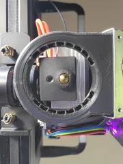
High-Flow Modular 5015 cooling duct sprite extruder
Description
PDFCreality Ender 3 S1
Creality Ender 3 S1 Pro
High Flow Modular 5015 cooling duct sprite extruder
This a more refined version of the Ender 3 S1 Twin Jet 5015 Fan Duct that is a little easier to print (less supports). It also doesn't require relocating the CR-Touch Probe with a “Zero-Y Backplate” (that's still optional if you like).
And it's more a new design. I didn't use any of parts or dimensions from the Twin Jet. As I tend to do, is I take a general idea, and start from scratch.
There should be ~1.5mm clearance from the nozzle tip to the bottom of all the lowest printed parts, so it should not interfere with any printed parts.
There are only really 2 major parts. The mounting plate, and the fan duct. A third part of an optional fan shroud is also available.
The fourth part is a generic coupler so you can have fun and create or adapt another duct system to this setup. The opening of the fan duct is centered on the nozzle, so if you want to make your own duct, just design one side (suggest left side to go around the CR-Probe first), then just mirror it to the other side.
The fan mounting plate reuses the 3 existing mounting screws from the stock 4010 fan, it has a wire channel on the back to conceal the wire. And is stepped away from the stepper motor to allow airflow and try to mitigate any electromagnetic interference.
There are two versions of the mounting plate available to print.
1. Uses M3x8 and M4x20 socket head cap screws that screw directly into the printed part (the threads are already modeled into the part).
2. The other allows you to use M3 and M4 injection molded threaded brass inserts (available from Amazon, Prusa, or CNC Kitchen) and again M3x8 and M4x20 socket head cap screws.
This second one is nice so one can quickly and easily remove the duct for easier access to the hot end for changing nozzles, cleaning, etc. The M4 threaded inserts are good for replacing the 5015-fan when it wears out (which they all do, eventually).
The fan duct is as simple of a duct as possible, but still directs a high volume of air over the nozzle and printed parts. Great for high flow hot ends.
*Please note that the openings on the fan duct look to be placed too far back, but that is needed to direct the air properly due to the design of the duct itself (see photos of “water test”). The openings have been placed far away from the nozzle/hot end to prevent any melting of the duct opens so it can be printed with standard PLA filament (I have tested the hot end up to 260 C with no visible melting of a PLA duct. One is welcome to use a different high temperature filament).
.step files off all parts are included for easier remixing in CAD.
Bill of Materials needed:
- 5015 24 Volt Axial blower fan (Amazon link to possible fans)
- 2 M3x8 socket head cap screws.
- 2 M4x20 socket head cap screws.
Optional:
- 2 M3 H6x4mm injection molding threaded brass inserts.
- 2 M4 H6x4mm injection molding threaded brass inserts.
Required Skills/tools:
Possible wire cutting and soldering, depending on which 5015 fan is purchased. You might have to cut the wires from the original 4010-fan (cut roughly in half to allow for easier holding and soldering) and splice the new 5015-fan wires to the original plug end of the 4010-fan.
If you plan on using the injection molding threaded brass inserts, you will need a soldering iron to melt the inserts into the mounting plate. Press the inserts in from the backside of the mounting plate, there are already chamfers in place to help guide the inserts in. (Please search the internet for instructions).
Print settings:
- Standard 0.4mm nozzle.
- Standard 0.2mm layer height.
- 4 walls/perimeters (to help with printing the duct and general strength).
- Tree supports on build plate for the duct.
- Infill is users' discretion.
- I recommend printing the mounting plate and fan cover on a non-texturized/smooth build plate (helps with sealing the duct to the mounting plate, makes the fan cover look nicer).
Assembly:
- Screw the fan duct to the mounting plate (make sure the screws do not protrude on the back and possible touch the stepper motor, shouldn't be an issue with the mounting holes on the fan duct, just check as a precaution)
- Remove the CR-Touch probe (2 M3 screws)
- Remove the existing 4010-fan cooling assembly. Keep the 3 existing M3 screws for later.
- Splice wires if needed.
- Connect the fan to the main PCB board.
- Route wires along with the existing wires to the front of the extruder stepper motor.
- Route wires in the back of the mounting plate in the recessed groove, under the three retaining tabs.
- Use the M3 screws from the old 4010-fan assembly to mount the new mounting plate.
- Slip the outlet of the 5015-fan into the cooling duct opening.
- Place optional fan cover over the 5015-fan assembly.
- Use 2 M4x20 screws to secure the 5015-fan/cover assembly.
- Re-attach the CR-Touch probe.
- Verify Z-offset and bed mesh (since you removed the CR-Touch probe).
- Change the dimensions of the print head in your slicer software (you will have to measure and look up on the proper settings for your preferred slicer software).
Tags
Model origin
The author remixed this model.


